Multiplexer
Multiplexer is a device that has
multiple inputs and a single output.
The select lines determine which
inputs is connected to the output and also to increase the amount of data that
can be sent over a network within certain time.It is also called a DATA SELECTOR.
A multiplexer is a combinational circuit that select binary information from one of many input line & directs it to a single output line.
Selection of particular i/p line is controlled by a set of selection lines.
A multiplexer is a combinational circuit that select binary information from one of many input line & directs it to a single output line.
Selection of particular i/p line is controlled by a set of selection lines.
Multiplexer contain:
v
2n data inputs
v
N selected input
v
A single output
v
Selection input determine the
input that should ne connected to the output.
Four
types of multiplexer:
1.
2-1 multiplexer
2.
4-1 multiplexer
3.
8-1 multiplexer
4.
16-1 multiplexer
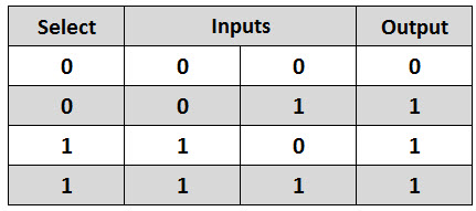
2-to-1 Multiplexer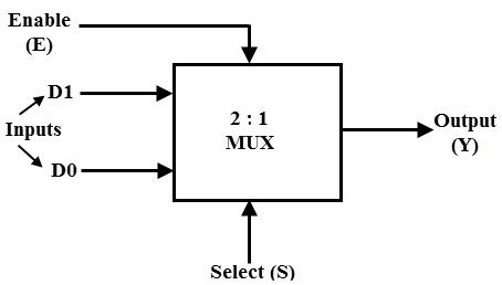
The truth table of the 2-to-1 multiplexer is shown below. Depending on the selector switching the inputs are produced at outputs , i.e., D0 , D1 and are switched to the output for S=0 and S=1 respectively . Thus, the Boolean expression for the output becomes D0 when S=0 and output is D1 when S=1.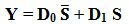
From the above output expression, the logic circuit of 2-to-1 multiplexer can be implemented using logic gates as shown in figure.
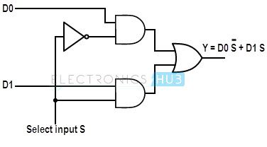 logic diagram of 2-to-1 multiplexer.
It consists of two AND gates, one NOT gate and one OR gate. When the select line, S=0, the output of the upper AND gate is zero, but the lower AND gate is D0.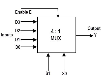
The truth table of a 4-to-1 multiplexer is shown below in which four input combinations 00, 10, 01 and 11 on the select lines respectively switches the inputs D0, D2, D1 and D3 to the output.
That means when S1=0 and S0 =0, the output at Y is D0, similarly Y is D1 if the select inputs S1=0 and S0= 1 and so on.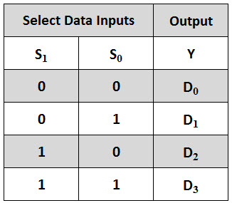
From the above truth table, we can write the output expressions as From the above expression of the output, a 4-to-1 multiplexer can be implemented by using basic logic gates. The below figure shows the logic circuit of 4:1 MUX which is implemented by four 3-inputs AND gates, two 1-input NOT gates, and one 4-inputs OR gate.
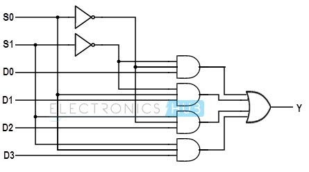 This is the logic diagram of 4-to-1 multiplexer
8-to-1 Multiplexer
This is the logic diagram of 4-to-1 multiplexer
8-to-1 Multiplexer
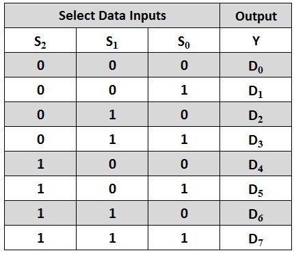
An 8-to-1 multiplexer consists of eight
data inputs D0 through D7, three input select lines S2 through S0 and a single
output line Y. Depending on the select lines combinations, multiplexer decodes
the inputs.
The below figure shows the block diagram of
an 8-to-1 multiplexer with enable input that enable or disable the multiplexer.
Since the number data bits given to the MUX are eight then 3 bits (23=8) are
needed to select one of the eight data bits.

The truth table for an 8-to1 multiplexer is
given below with eight combinations of inputs so as to generate each output
corresponds to input.
For example, if S2= 0, S1=1 and S0=0 then
the data output Y is equal to D2. Similarly the data outputs D0 to D7 will be
selected through the combinations of S2, S1 and S0 as shown in below figure.
From the above truth table, the Boolean
equation for the output is given as

From the above Boolean equation, the logic circuit diagram of an 8-to-1 multiplexer can be
implemented by using 8 AND gates, 1 OR gate and 7 NOT gates as shown in below
figure. In the circuit, when enable pin is set to one, the multiplexer will be
disabled and if it is zero.
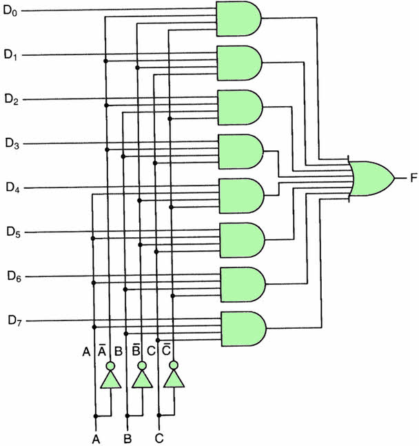
This
is the logic diagram of 8-1 multiplexer.
16-to-1 Multiplexer
We implement 16x1 Multiplexer using 8x1 Multiplexers and 2x1
Multiplexer. We know that 8x1 Multiplexer has 8 data inputs, 3 selection lines
and one output. Whereas, 16x1 Multiplexer has 16 data inputs, 4 selection lines
and one output.
So, we
require two 8x1 Multiplexers in first stage in order to get
the 16 data inputs. Since, each 8x1 Multiplexer produces one output, we require
a 2x1 Multiplexer in second stage by considering the outputs of first stage as
inputs and to produce the final output.
Let the
16x1 Multiplexer has sixteen data inputs I15 to I0,
four selection lines s3 to s0 and one output Y.
The Truth table of 16x1 Multiplexer is shown below.
Selection Inputs
|
Output
|
|||
S3
|
S2
|
S1
|
S0
|
Y
|
0
|
0
|
0
|
0
|
I0
|
0
|
0
|
0
|
1
|
I1
|
0
|
0
|
1
|
0
|
I2
|
0
|
0
|
1
|
1
|
I3
|
0
|
1
|
0
|
0
|
I4
|
0
|
1
|
0
|
1
|
I5
|
0
|
1
|
1
|
0
|
I6
|
0
|
1
|
1
|
1
|
I7
|
1
|
0
|
0
|
0
|
I8
|
1
|
0
|
0
|
1
|
I9
|
1
|
0
|
1
|
0
|
I10
|
1
|
0
|
1
|
1
|
I11
|
1
|
1
|
0
|
0
|
I12
|
1
|
1
|
0
|
1
|
I13
|
1
|
1
|
1
|
0
|
I14
|
1
|
1
|
1
|
1
|
I15
|
We can
implement 16x1 Multiplexer using lower order Multiplexers easily by considering
the above Truth table. The block diagram of 16x1 Multiplexer
is shown in the following figure.
The same
selection lines, s2, s1 & s0 are
applied to both 8x1 Multiplexers. The data inputs of upper 8x1 Multiplexer are
I15 to I8 and the data inputs of lower 8x1
Multiplexer are I7 to I0. Therefore, each 8x1
Multiplexer produces an output based on the values of selection lines, s2,
s1 & s0.
The
outputs of first stage 8x1 Multiplexers are applied as inputs of 2x1
Multiplexer that is present in second stage. The other selection line,
s3 is applied to 2x1 Multiplexer.
·
If s3 is zero,
then the output of 2x1 Multiplexer will be one of the 8 inputs Is7to
I0 based on the values of selection lines s2, s1 &
s0.
·
If s3 is one,
then the output of 2x1 Multiplexer will be one of the 8 inputs I15 to
I8 based on the values of selection lines s2, s1 &
s0.
Therefore,
the overall combination of two 8x1 Multiplexers and one 2x1 Multiplexer
performs as one 16x1 Multiplexer.
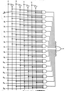
This is
the logic diagram of 16-to-1 multiplexer.